 English
 Français
 Deutsch
 euskara
 Русский язык
 Italiano
 Português
 Nederlands
 Polski
 Greek
Greek Lietuva
 Türkçe
 日本語
日本語 한어
한어 中文
中文 தாமில்
 فارسی
فارسی हिंदी
हिंदी Tiếng Việt
 ภาษาไทย
 Pilipino
 Indonesia
 தாமில்
Send us a message
CLOSE
WhatsApp: +65 91904616 E-mail: sales@sintec.sg


Laser beam profiling plays an important role in such applications as laser welding, laser focusing, and laser free-space communications. In these applications, laser profiling enables to capture the data needed to evaluate the change in the beam width and determine the details of the instantaneous beam shape, allowing manufacturers to evaluate the position of hot spots in the center of the beam and the changes in the beam’s shape.
Digital wavefront cameras (DWC) with software can be used for measuring laser beam propagation parameters and wavefronts in pulsed and continuous modes, for lasers operating at visible to far-infrared wavelengths:
beam propagation ratio M²;
width of the laser beam at waist w0;
laser beam divergence angle θx, θy;
waist location z-z0;
Rayleigh range zRx, zRy;
Ellipticity;
PSF;
Wavefront;
Zernike aberration modes.
These parameters allow:
- controlling power density of your laser;
- controlling beam size, shape, uniformity, focus point and divergence;
- aligning delivery optics;
- aligning laser devices to lenses;
- tuning laser amplifiers.
Accurate knowledge of these parameters can strongly affect the laser performance for your application, as they highlight problems in laser beams and what corrections need to be taken to get it right.

Figure 1. Characteristics of a laser beam as it passes through a focusing lens.
M², or Beam Propagation Ratio, is a value that indicates how close a laser beam is to being a single mode TEM00 beam. This in turn relates to how small a spot a laser can be focused. For a laser beam propagating through space, the equation for the divergence, Θ, of a pure Gaussian TEM00 unfocused beam is given by:
Θ00 = 4λ/πD00 (1)
where D00 is the waist diameter of the beam, and λ is the wavelength. Actual beams with additional modes often start with a larger beam waist, D0, and/or have a faster divergence Θ0. In this case Equation (1) becomes:
Θ0 = M2 4λ/πD0 (2)
where Θ0 and D0 are the divergence and width of a higher mode beam and M² is greater than 1 and is named the “Beam Propagation Ratio” per the ISO 11146 standard. When a pure Gaussian laser beam is focused, the diameter of the focused spot is defined by:
d00 = 4λf /πD00 (3)
where D00 is the ideal focused spot diameter, f is the focal length of the lens, and is placed one focal length from the lens as shown in the Figure 1. However, when a distorted or multimode beam is focused, Equation (3) becomes:
d0 = M2 4λf / πD0 (4)
Apart from M², the measured beam propagation parameters characterizing laser beams are:
w0 = d0/2– the waist radius in X (horizontal) and Y (vertical) directions;
z-z0 – the distance between measurement and waist planes;
zR – the Rayleigh range, for which the radius of curvature R of the wavefront is minimal;
θ – the divergence angle of the measured laser beam far from the waist;
R – the radius of curvature of the wavefront in the measurement plane.

3.1 Principle
Propagation parameters are measured by DWC on real beams by focusing the beam with a fixed position lens of known focal length, and then measuring the characteristics of the artificially created beam waist and divergence.
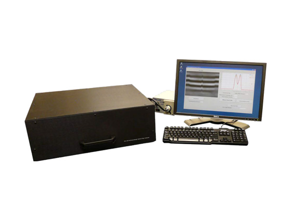
Measurement of the beam propagation parameters with DWC is based on the simultaneous measurement of the high-resolution images of intensity and wavefront. The wavefront is computed starting from two slightly defocused beam intensity images acquired on one CCD camera inside DWC by mathematical computations involving the two images and the difference between them (Figure 2). From the wavefront, the beam propagation parameters are obtained by straightforward but tedious computations.

Figure 2. Principle of DWC: Acquisition of two images in real time at two different focal planes, wavefront extraction and computation of beam propagation parameters.

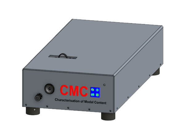
Figure 3. DWC and the Graphic User Interface of its associated software.
3.2 System Set-up

Figure 4. Example of a setup for measurement of laser propagation parameters with DWC.

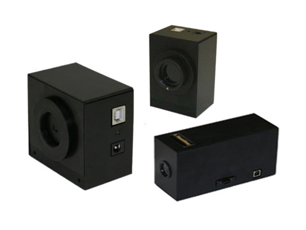
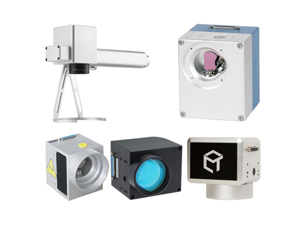
VIS/NIR Beam Profiler: STCam CCD

Our CCD is developed to provide excellent sensitivity from the VIS to NIR spectral range. Thanks to its high resolution and its small pixel size, the STCam is a high performance tool for laser beam analysis of continuous wave (CW) and pulsed laser modes. Due to its high dynamic range the STCam captures even higher laser modes with outstanding detail.
The passive cooled sensor of the STCam is constructed without cover glass to avoid interference patterns. For sensor protection a low distortion neutral density filter is integrated. The STCam supports the ultra-fast FireWire IEEE 1394b interface with data transfer rates up to 800 Mbit/s. The plug and play design facilitates easy and flexible integration and operation.
The portable STCam is designed to be used in a variety of applications in industry, science, research and development, including:
Laser beam analysis of CW and pulsed lasers,
Quick control of laser modes and adjustment errors,
Test equipment for scientific research,
Near-Field and Far-Field analyses of lasers, LED devices and other light sources.
The enhancement of product quality, process reliability and efficiency are just a few of the many benefits of our unique beam profiler cameras. The STCam includes the specifically designed analysis software, STRayCi, which supports Windows XP/Vista operating systems. Its sophisticated software architecture opens up new opportunities in laser beam analysis according to ISO standards.
The concept of the STCam enables easy adaption to standard optical imaging systems, attenuators and opto-mechanical components ensuring highest flexibility. This includes:
Microscope lens and beam expander,
UV-Converter and IR-Converter,
Fixed and variable attenuators, etc.
ACCESSORIES
Neutral Density Filter: To expand the power range of the STCam several absorptive and metallic-coated neutral density filters are available, which are specified by optical densities ranging from OD 1.0 to OD 4.0.
FireWire Component: We offer different FireWire PCI / PCI Express cards for installation direct into the PC. Standard FireWire cables are suitable for industrial applications and are available in various lengths.
Trigger Device: To synchronize the STCam with pulsed laser systems, our trigger device is perfectly suited. This frequency and delay generator is software controllable and enables the synchronization of up to four beam profilers with different delay times simultaneously.
CCD-1201 | CCD-2301 | CCD-2302 | |
SENSOR DATA | |||
Format | 1/2” | 2/3” | 2/3” |
Active area | 6.5x4.8mm | 9.0x6.7mm | 8.5x7.1mm |
Number of pixel | 1388x1038 (1.4MPixel) | 1388x1038 (1.4MPixel) | 2452x2056 (5MPixel) |
Pixel size | 4.65x4.65μm | 6.45x6.45μm | 3.45x3.45μm |
Spectral response without cover glass | 350-1100nm | 350-1100nm | 350-1100nm |
Laser beam diameter min/max | 46.5/4mm | 64.5μm/5mm | 34.5μm/5.5mm |
Sensor cooling | passive | passive | passive |
CAMERA FEATURES | |||
Lens Mount | C-Mount | C-Mount | C-Mount |
Bit depth (output) | 14Bit | 14Bit | 14Bit |
Dynamic (signal to noise) | 60dB (1:1000) | 67dB (1:2200) | 54dB (1:500) |
Frame rate | up to 15Hz | up to 16Hz | up to 9Hz |
Exposure time | 100μs-1s | 100μs-1s | 100μs-1s |
Interface | FireWire (IEEE1394b) | FireWire (IEEE1394b) | FireWire (IEEE1394b) |
I / O connector | 12-Pin Hirose | 12-Pin Hirose | 12-Pin Hirose |
Mode | CW or pulsed | CW or pulsed | CW or pulsed |
Trigger | TTL-signal | TTL-signal | TTL-signal |
Combinable with | IR-/UV-Converter Beam expander Attenuator | Beam expander Attenuator | Beam expander Attenuator |
SPECIFICATIONS | |||
Mechanical dimensions (WxHxL) | 60x60x103.8mm | 60x60x103.8mm | 60x60x103.8mm |
Weight | 300g | 300g | 300g |
Electrical requirements | DC 8V-36V | DC 8V-36V | DC 8V-36V |
Storage temperature* | -10°C…+60°C | -10°C…+60°C | -10°C…+60°C |
Operating temperature* | +5°C…+45°C | +5°C…+45°C | +5°C…+45°C |
Regulations | CE, RoHS | CE, RoHS | CE, RoHS |
* without condensation
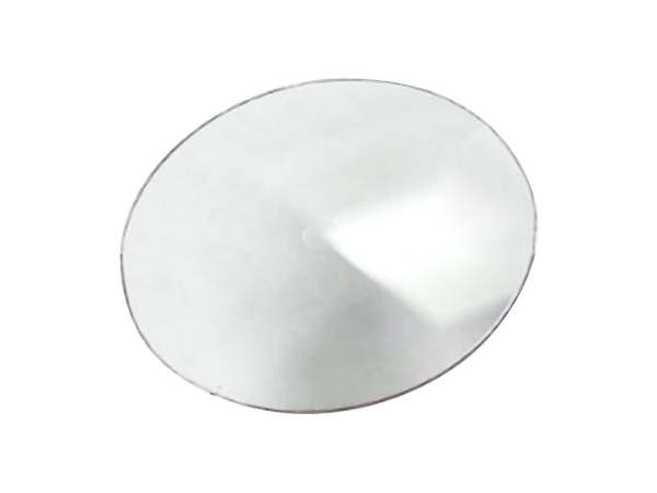
Neutral Density Filter

Our neutral density filters allow broadband attenuation for a spectral range from VIS to NIR. Due to their excellent surface quality the absorptive and reflective filters enable precise beam attenuation for low power applications. The level of attenuation is specified by the optical density. Filters with different optical densities can be combined. A filter adapter is available to mount the filters on the STCam aperture.
Reflective ND filter | Absorptive ND filter | |
NDR-10 / NDR-20 / NDR-30 / NDR-40 | NDA-10 / NDA-20 / NDA-30 / NDA-40 | |
Optical density* | 1.0 / 2.0 / 3.0 / 4.0 | 1.0 / 2.0 / 3.0 / 4.0 |
Spectral range | 200nm - 1200nm | 400nm - 700nm / 700nm - 1200nm |
Material | UV-Fused silica (Coating: Metal) | Schott glass |
Flatness | 1λ @ 300nm | λ/10 @ 632.8nm |
Scratch-Dig | 40 - 20 | 40 - 20 |
Parallelism: | 3arcmin | 10arcsec |
Optical density tolerance | ±5% | ±5% |
Power (Pmax) | < 1W | < 1W |
Intensity (Imax) | 0.75W/cm2 | 1W/cm2 |
Diameter | ∅=25mm/25.4mm | ∅=25mm/25.4mm |
Operating temperature | < 100°C | < 100°C |
Filter threads | Filter thread / Filter mount | Filter thread / Filter mount |
Filter adapter | C-Mount thread / Filter thread | C-Mount thread / Filter thread |
Laser Beam Profiling Software STRayCi

Our sophisticated beam profilers are available with the specifically designed analysis software, STRayCi, which supports Windows XP/Vista operating systems. It is available as 32 Bit / 64 Bit version and can control up to eight beam profiler cameras on a single computer.
Due to its clearly designed menu structure, STRayCi shows self-explanatory functions, which help the user to access quickly standard settings. Incomparable visualization modes, extensive analytical capabilities as well as new developed correction algorithms ensure the highest accuracy in laser beam analysis.
A wide range of beam width techniques e.g. 2nd Moment, Knife Edge, Moving Slit, Plateau, Gauss-Fit can be applied to determine quick and reliable standard beam parameters. The unique measurement tool enables the continuous monitoring of beam parameters, beam position and power density distribution. Helpful features like AOI Tracking, AOI Optimization, Zoom Functions, Look-Up Tables, etc. simplify the laser beam analysis.
The extraordinary graphical and analytical tool of STRayCi can be used for live data (LiveMode) and stored data (SaveMode) simultaneously, while each mode has its own individual functions. This makes STRayCi the most advanced analysis software on the market.
STRayCi is equipped with flexible data and image output capabilities. This permits the user to store data and images in the format that is compatible with their needs.
A clearly arranged and printable protocol view displays the chosen measurement parameters as well as the most important laser beam analysis results.
STRayCi is compatible with guidelines of the international standard organization for laser beam measurements:
ISO 11145: Vocabularies and symbols
ISO 11146: Beam width, propagation ratio,…
ISO 11670: Beam positional stability,…
ISO 13694: Beam power density distribution,…
STRayCi works only with a USB software protection lock. It is a hardware based security solutions to protect and encrypt the software against piracy.
MINIMUM SYSTEM REQUIREMENTS:
Windows XP / Vista
Pentium IV / AMD Processor
128 MB graphic card, Open GL V1.4 compatible
100 MB free memory
PCI / PCIe slot for FireWire card
USB port for dongle connection
CD / DVD-ROM drive for software installation
Internet access for update request

STRayCi Special Features
REAL-TIME BEAM PROFILING
2D / 3D intensity plots / Cross sections / Histogram
Pointing stability (x-y fluctuation, COG- position analysis, ect.)
Parameter stability (intensity, power, center x-y, beam size)
Parameter results (beam statistics, beam width, beam parameter)

CAMERA CONTROL
Multiple camera support
Different measure types
User-selectable exposure time and gain factor, auto-exposure time
Floating average and variable brightness
ANALYSIS FUNCTIONS
Beam statistics (power, max intensity, COG, etc.)
Beam width (2nd Moment, Gauss / Super-Gauss-Fits, Plateau, Knife Edge, Moving Slit, ect.)
Beam parameter (beam width, ellipticity, uniformity, etc.)
CALIBRATION AND CORRECTION TOOL
Background subtraction, auto-background
Pixel correction technology (offset correction, linearity, etc.)
Power calibration
OTHER FEATURES
User-defined Area of Interest (AOI)
AOI tracking and optimization
Color palettes incl. auto-contrast function
Zoom functions
2D profile arithmetic operations, filters, transformations, etc.
E-mail support
FLEXIBLE OUTPUT
Data: txt, tiff
Image: jpeg, png, bmp, gif, tiff
Protocol: pdf

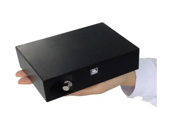
Measurement of Beam Diameter, Divergence & Energy Distribution

Laser profile analyzer is adopted to measure laser transverse mode energy distribution. One-dimensional, two-dimensional and three dimensional energy distribution will be shown on the software, as well as laser transverse mode characteristics of spot diameter, beam divergence, ellipticity and etc.
The software can provide four calculation method of measured results of laser spot diameter, one of the most widely used definition method is 13.5% of peak value as the boundary (1/e2), and the beam ellipticity definition is the ratio of 4 Sigma spot diameter on minimum direction and 4 Sigma spot diameter on maximum direction.
Laser beam divergence is a physical parameter to describe laser divergence degree, the measurement method is roughly summed up as measuring beam spot diameters both on near field and far field, by calculating the distance between the two spot diameter deviation of the two positions of tangent value, which can determine the divergence angle value, then converted into spacial angle value.
Technical Specifications:
Part number | STC-DD |
Wavelength range | 350-1320nm |
Maximum sensor diameter | 9mm |
Measurement accuracy | ±2% |
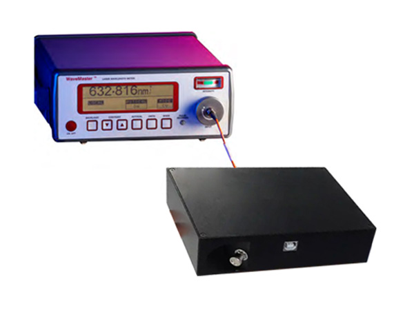
Display of Measurements


Laser beam quality and its focusing capability are very important parameters of a laser and are usually characterized by M² factor. To measure the M² factor for a laser, it is calculated based on the difference between the product of the beam diameter and divergence, and the ideal Gaussian beam diffraction limit. The laser beam quality M2 is as below:

Where M2 is the laser beam quality M2, π is 3.1415927, λ is laser wavelength, d0 is beam diameter, and θis divergence angle.
Part number | STC-M2 |
Detector material | Si |
Wavelength range | 400-1100nm |
Receiving beam diameter | 20um-9mm |
Testing output power range | 10nW-10W(Depends on the beam diameter) |
The system comes with software. After the positions are keyed in the software, the beam diameters and M2 will be calculated and given as shown as follows:

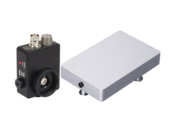
With an 11.3 x 11.3 mm active area, 4.2 Mpixels, 5.5 x 5.5 µm pixels, optical and electronic triggering of a global shutter, and an update rate to 60+ Hz, the SDR-WCD-LCM series is ideally suited to both CW and pulsed laser beam profiling. The high resolution CMOS detector means no comet tailing, and the shutter and trigger options simplify pulse capture.
The SDR-WCD-LCM is paired with a full-featured software which has no license fees, unlimited installations, and free software updates. It is ideal for applications including: CW and pulse laser profiling; field servicing of laser systems; optical assembly; instrument alignment; beam wander and logging; R&D; OEM integration; quality control; and M2 measurement with available M2DU stages.

System Features:
355 – 1150 nm (CMOS)
-TEL sensor options for 1480-1610 nm
-UV and 1310 nm options available
4.2 MPixel, 2048 x 2048 pixels, 11.3 x 11.3 mm active area
5.5 µm pixels
60 fps @ 512 x 512, 30 fps @ 1024 x 1024, 12 fps @ 2048 x 2048
Port-powered USB 3.0
HyperCalTM – Dynamic Noise and Baseline Correction software.
MagNDTM stackable magnetic ND filters or C-mount filters
2500:1 signal to RMS Noise
Global shutter with TTL trigger
Electronic auto-shutter, 85 µs to 2 sec (44dB)
12-bit ADC
Isolated pulse triggering
Parallel capture on multiple cameras
Field-replaceable image sensors
Relative power level display
Window-free sensor standard for no fringing
ISO 11146 M2 option – beam propagation analysis, divergence, focus
Available in specialized beam profiler systems
-Industrial Laser Monitoring System (ILMS)
-Large Beam Profiling system (LBPS)
-Line Laser Profiling System (LLPS)
Applications:
CW & pulsed laser profiling
Field servicing of lasers and laser-based systems
Optical assembly & instrument alignment
Beam wander & logging
M2 measurements
Additional software features:
XY profiles and centroids
Linear and logarithmic displays
Gaussian and Top Hat least squares fits
Ellipse Angle, Major, Minor, Mean Diameters
ISO 11146 compliant
Background capture and subtraction
Image & Intensity Zoom
Linear and area filters
Image Averaging, 1 to continuous
Proprietary HyperCalTM Dynamic Noise and Baseline Correction
Model Specifications:
Specification | Detail | Notes |
wavelength range: | SDR-WCD-LCM-UV:190–1150 nm | Incl. MagND-UV filters: ND 1, 2, 4 and MagND filters: ND 1, 2, 4 |
SDR-WCD-LCM: 355-1150 nm | Incl. MagND filters: ND 1, 2, 4 | |
SDR-WCD-LCM-1310:355-1350nm | Incl. MagND filters: ND, 1, 2, 4, 1290 nm longpass filter | |
SDR-WCD-LCM-TEL:1480-1610nm | Incl. MagND filters: ND 1, 2, 4, 1290nm longpass filter | |
Image area (mm) | 11.3 x 11.3 | |
Sensor | 1” CMOS | |
Resolution | 4.2 MPixel (2048 x 2048) | |
Pixel dimensions (µm) | 5.5 x 5.5 | SDR-WCD-LCM-TEL: effective pixel size is 25 µm |
Min. beam (10 pixels) | 55 µm | SDR-WCD-LCM-TEL: 250µm |
Shutter type | Global | |
Frame rate @ 2048x2048 | ≥ 12Hz | |
Frame rate @ 1024x1024 | ≥ 30Hz | |
Frame rate @ 512x512 | ≥ 60Hz | |
Max. “every pulse’ PRR | USB 3.0: 12.6 kHz USB 2.0: 6.3 kHz | |
Beam Diameter Accuracy | ±2% (when used as specified) | |
Signal to RMS Noise | 2500:1, 34/68 dB opt/elec. | |
Electronic shutter | 25000:1, 85µs to 2s USB3.0 12500:1, 158µs to 2s USB 2.0 | |
ADC | 12-bit | |
Interface | USB3.0 |
Outline & Mounting:

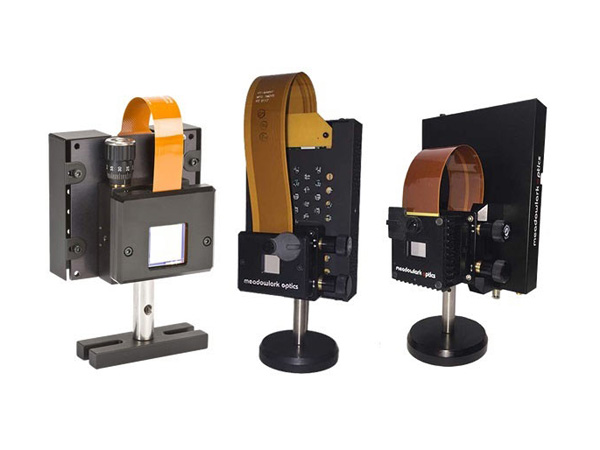
With pixels as small as 3.2 µm, the high resolution and highly compact SDR-BC2 beam profilers have a thickness of only 0.50” (12.84mm) for insertion into tight optical trains and OEM applications.

System Features:
355 – 1150 nm, CMOS detector
-TEL sensor options for 1480 – 1610 nm
-UV and 1310 nm options available
Two sensor pixel size/resolution options
-SDR-BC2-XHR: 3.2µm pixels, 3.1 MPixel, 2048 x 1536
-SDR-BC2-HR: 5.2µm pixels, 1.3 MPixel, 1280 x 1024
6 fps @ 2048 x 1526, 16 fps @ 1024 x 1024, 35 fps @ 512 x 512
Port-powered USB 3.0
HyperCalTM – Dynamic Noise and Baseline Correction
C-mount filters included
1000:1 signal to RMS noise
CW/Quasi-CW
Electronic auto-shutter, 40µs – 1s (XHR) or 40µs – 500 ms(HR)
10-bit ADC
Parallel capture on multiple cameras
Field-replaceable image sensors
Relative power level display
Window-free sensors standard for no fringing
ISO 11146 M2 option – beam propagation analysis, divergence, focus
Applications:
CW/Quasi-CW
Field servicing of lasers and laser-based systems
Optical assembly and instrument alignment
Bam wander and logging
M2 measurements
Small form factor for tight optical trains
Model Specifications:
SDR-BC2TM | SDR-BC2-XHR | SDR-BC2-HR | SDR-BC2-HR-TEL | |
Pixel count | 3.2 MPixel | 1.3 MPixel | ||
H x V | 2048 x 1536 | 1280 x 1024 | ||
Sensor image area (mm) | 6.5 x 4.9 | 6.6 x 5.3 | ||
Pixel dimension (µm) | 3.2 x 3.2 | 5.2 x 5.2 | 25 (due to phosphor) | |
Min. beam (10 pixels) | 32 µm | 52 µm | 250 µm | |
wavelength range | 355 – 1100 nm | 1480 – 1680 nm | ||
Shutter type | Rolling | |||
Max frame rate: Frame rate @ 2048 x 1536 | > 6Hz | N/A | ||
Frame rate @ 1024 x 1024 | >16 Hz | |||
Frame rate @ 512 x 512 | >35 Hz | |||
Max. ‘every pulse’ PRR | Not suitable for pulse capture | |||
Single pulse capture PRR | Not suitable for pulse capture | |||
Signal to RMS Noise (Optical/Electrical) | 1000:1 (30/60 dB) | |||
Electronic shutter dynamic range | 40 µs to 1 s 44dB | 40 µs to 500ms 41 dB | ||
ADC | 10-bit | |||
Interface | USB 3.0/2.0 | |||
Outline and Mounting:


With a large 25 x 25 mm active area, 4.2 Mpixels, 12.5 x 12.5 μm (effective) pixels, optical and electronic triggering of a global shutter, and an SNR of 2500:1, the SDR-TCD-LCM beam profiler offers the largest active sensor area on a USB-port powered laser beam profiling device. By combining the high signal-to-noise ratio and global shutter of the SDR-WCD-LCM with a high-quality fiber optic taper, the SDR-TCD-LCM offers a very compact, easy-to-use solution for measuring a variety of large CW or pulsed lasers.
The SDR-TCD-LCM is paired with our full-featured, highly customizable, user-centric software (which has no license fees, unlimited installations, and free software updates). It is perfect for applications including: CW and pulsed laser profiling; field servicing of laser systems; optical assembly; instrument alignment; beam wander and logging; R&D; OEM integration; and quality control.
System Features:
355 - 1150 nm (CMOS)
4.2 MPixel, 2048 x 2048 pixels, 25 x 25 mm active area
12.5μm (effective) pixels
2,500:1 Signal to RMS Noise
60 fps @ 512 x 512, 30 fps @ 1024 x 1024, 12 fps @ 2048 x 2048
Port-powered USB 3.0
HyperCal™ – Dynamic Noise and Baseline Correction software
Includes 2" NDXL ND filters
Global shutter with TTL trigger
Electronic auto-shutter, 85μs to 2 sec (44 dB)
12-bit ADC
Isolated pulse triggering
Parallel capture on multiple cameras
Relative power level display
Applications
CW & pulsed laser profiling
Field servicing of lasers and laser-based systems
Optical assembly & instrument alignment
Beam wander & logging

Our SDR-Beam'R2 is well suited for many laser beam profiling applications. With both standard 2.5μm slits and larger knife-edge slits, the SDR-Beam'R2 is capable of measuring beams with diameters as small as 2μm. With options for both silicon and InGaAs or extended InGaAs, the SDR-Beam'R2 can profile beams from 190 nm to 2500 nm. Scanning slit instruments offer much higher resolution than camera-based systems.
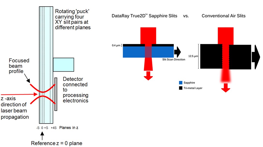
Our SDR-BeamMap2 represents a radically different approach to real-time beam profiling. It extends the SDR-Beam'R2’s measurement capabilities by allowing for measurements at multiple locations along the beam’s travel. This real-time slit scanning system uses XY slit pairs in multiple z planes on a rotating puck to simultaneously measure four beam profiles at four different z locations. The SDR-BeamMap2’s unique, patented design is most advantageous for real-time measurement of focus position, M2, beam divergence and pointing.
System Features:
ISO compliant beam diameter measurements
Port-powered USB2.0
Auto-gain function
Optional stage accessory for ISO 11146 compliant M2 measurements.
True2D slits
Resolution up to 0.1μm
Detector options, 190 – 2500 nm
5 Hz update rate (user adjustable 2-12 Hz)
Measure high repetition pulsed lasers
Pulsed Minimum PRR = [500/(beam diameter in μm)] kHz

BeamMap2 adds the following features
Multiple z-plane scanning
XYZ profiles, plus θ-Φ
Focus position and diameter
Real-time M2, Pointing, and Divergence
Measure divergence of well-collimated beam in real-time with BeamMap2-Collimate
Identify focus with ±1μm repeatability (beam dependent)
Optional LensPlate2 for reaching inaccessible beam waists and reimaging waveguides
Applications
Very small laser beam profiling
Optical assembly and instrument alignment
OEM integration
Lens focal length testing
Real-time diagnosis of focusing and alignment errors
Real-time setting of multiple assemblies to the same focus
True2D Slits
0.4μm thick metallic multilayer films on a sapphire substrate
Advantages over air slits
Avoid tunnel effect
Air slits are typically deeper than they are wide, and can buckle under high irradiance
Specifications:
Parameter | Specification | SDR-BeamMap2 | SDR-Beam'R2 | Comments |
Wavelength options: | 190-1150 nm, 650-1800 nm, 190-1800 nm, 190-2500 nm | Yes | Yes | Si, InGaAs, Si + InGaAs, Si + InGaAs, extended |
Scanned beam diameters: | 2μm to 4 mm (2 mm for IGA-X.X) | Yes | Yes | |
X-Y Profile & Centroid Resolution: Accuracy: | 0.1μm or 0.05% of scan range ± <2% ± ≤0.5μm | Yes | Yes | |
CW or Pulsed | CW, Pulsed Minimum PRR ≈ [500/(Beam diameter in μm)]kHz | Yes | Yes | |
Beam alignment: | ± 1 mrad with BeamMap2 ColliMate | Yes | - | Beam Dependent |
M2 measurement: | 1 to >20, ± 5% | Yes | - | 4 Z-plane hyperbolic fit |
Real-time update: | 5 Hz | Yes | Yes | Adjustable 2-12 Hz |
Maximum Power & Irradiance: | 1 W Total & 0.3 mW/μm2 | Yes | Yes | Metallic film on Sapphire slits |
Gain Range: | 32dB | Yes | Yes | 12-bit ADC |
Display graphics: | All: X-Y position; Profiles. BeamMap2 only: M2, Focus; Divergence, Boresight/Pointing | |||
Extends the range of our standard silicon cameras into the near-infrared 1480 to 1605nm
No image fading or lag time
Cost effective for beams ≥ 500μm
High quality AR coated optics
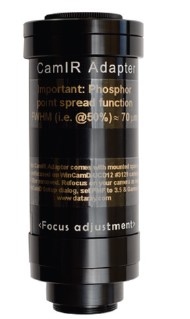
Applications: The CamIR Adapter* extends silicon camera sensitivity into the near IR range 1480-1605 nm, the telecom C, L & S* bands. This C-Mount module attaches to our standard cameras.
Technology: A proprietary phosphor converts 1480-1605 nm photons to Silicon CMOS/ CCD detectable wavelengths image to the attached CMOS/CCD camera at a demagnification of x0.29 (PMF=3.5) to give an effective active area of 22 x 16.5 mm with a ½", 1/1.8", ⅔", or 1" cameras.
The effective pixel size is 3.5 x the actual pixel size, but due to the phosphor, the primary limitation is the phosphors point spread function of ~70μm FWHM, and ~200μm at 1/e2.
The response to incoming irradiance is logarithmic. This is automatically corrected in our software, by setting the Gamma in Setup to 1.41. Like any phosphor, the response is spatially non-uniform. Typical beam diameter measurement accuracy is around 5 to 10%.
Performance and Pricing: This technology is better than the low resolution and image lag of IR vidicons, yet less sensitive and less uniform than InGaAs arrays.

*S-band: 1460 - 1530, C-band: 1530 - 1565, L-band: 1565 - 1625
Technical Specifications: | |
Optical Characteristics | |
Active Area | 27.5 mm |
IR Spectral Sensitivity | 1480 - 1605 nm (see curve) |
Peak IR Sensitivity | 1510/1540 nm (see curve) |
Maximum Resolution | 12lp/mm over active area |
Converter IR Output | 950 - 1075nm |
Distortion | -1.0% Barrel Distortion (Inverted Image) |
Linearity | Non-Linear IR converter output ~ (IR input intensity)1.41 |
Maximum Illumination | 1W/cm2 (damage may occur if this limit is exceeded) |
Other Characteristics | |
Dimensions | Φ 46 mm x L 97 mm |
Operating Temperature | -10⁰ C to +40⁰ C |
Weight | 210g |
Requirements | |
Mount | C-Mount (adapter supplied) |
Effective Aperture | 17 mm, 19 mm, 23 mm, 27.5 mm |
Camera Format | ½", 1/1.8", ⅔", 1" formats |
Application Areas
Beam intensity profiling of telecom diodes/devices
Imaging optical outputs of components such as optical fiber ends, amplifiers, routers and switchers, fiber gratings, splitters and couplers
On Line Production Alignment and Characterization –Real time Lens focusing
Stability Testing- Beam Wander over time
Divergence measurements
Co-Linear Measurements Aligning two lasers
Multiple Image separation Measurements (distance between peaks)
Measure Relative Intensity
For researchers requiring higher resolutions. We offer the phosphor coating applied directly onto the sensor. This improves the point spread function to ~ 35μm FWHM.
This option is offered on the following cameras:
Model | Description |
SDR-WCD-LCM1-NIR | 1” CMOS USB 3.0/2.0 system with phosphor coating for 1480 to 1605nm. |
SDR-WCD-UHR-NIR | ½” CMOS system with phosphor coating for 1480 to 1605 nm. |
SDR-BladeCam-UHR-NIR | ½” CMOS system with phosphor coating for 1480 to 1605 nm. |
SDR-WCD-UCD12-NIR | ½” CCD system with phosphor coating for 1480 to 1605 nm. |
SDR-WCD-UCD23-NIR | ⅔” CCD system with phosphor coating for 1480 to 1605 nm. |
SDR-TCD20-15-UCD23-NIR | 20 x 15 mm CCD system with phosphor coating for 1480 to 1605 nm. |
The SDR-ILMS is designed for profiling focused, high-power industrial lasers. This system combines reimaging/magnification optics, a polarization preserving beam sampler, and a DataRay beam profiler to measure small beam waists which would otherwise damage a traditional profiling system. Magnification of the focused beam allows full pixel-by-pixel 2D measurements of beam spots as small as a few microns.
The SDR-ILMS is compatible with most DataRay profilers and supported by the full-featured, highly customizable, and user-centric software (included without licensing fees). The software automatically accounts for the magnification of the system, so results do not require post processing or corrections.

System Features:
lUV, visible, NIR, MWIR, SWIR, eSWIR and FIR options.
High magnification options available (50X and beyond)
High-power beams (handling up to kWs)
Three swappable filters for flexible, fine attenuation
Profiler easily removed from system for stand-alone use
Optional calibrated pinhole apertures
Integrated power meter and beam dumps available
Profiling beam waist diameters down to a few µm.
Applications:
Tightly focused beams, fiber ends, edge couplers, laser diodes and more.
High power laser cutting systems
Additive manufacturing
Quality control
Application Examples – Additive and Subtractive Manufacturing
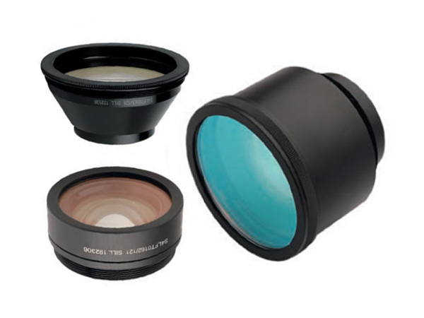
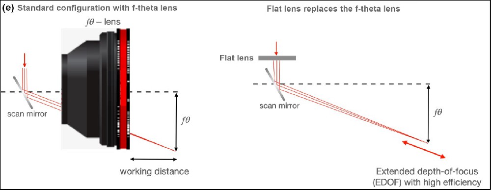
F-theta lenses are useful in additive and subtractive manufacturing for their ability to focus high-power beams over a range of XY locations at the focal plane. It is often useful to observe detailed 2D profiles of these focused beams.
Example: A 160-mm focal length F-theta lens focuses a 3.5-mm diameter collimated 343-nm laser to a minimum beam waist diameter of roughly 26 µm. The pixel size of traditional profiling cameras makes it challenging to accurately profile a waist this small. However, since the SDR-ILMS-5-UV utilizes magnification optics, full 2D profiles of tightly focused beam are possible, allowing you to diagnose hard-to-find issues such as hot spots or unexpected beam ellipticity.
Application Examples – Inaccessible Beam Waists
In many applications a beam waist is not accessible for measurements. Examples include the output facet of VCSELS, the end of optical fibers, or short working distance focusing optics. The SDR-ILMS easily reimages inaccessible beam waists making it possible to tackle these difficult applications.
Example: We need to profile the end of a 7-µm core diameter, single mode fiber being used with a 1064-nm fiber-coupled source. The optics in our SDR-ILMS-50-1064 magnify the fiber end onto a SDR-WCD-LCM. It is challenging to position a traditional profiler close enough to the fiber for near-field profiling.
Standard Configurations:
Model | Magnification | AR coating wavelength (nm) | Input NA | System Dimensions (mm) | Typical spot size (1/e2, µm) |
SDR-ILMS-5-UV | 5x | 250-425 | 0.17 |
70.0 x 133.3 x 176.3 | 11 |
SDR-ILMS-5-VIS | 5x | 425-675 | 0.17 | 11 | |
SDR-ILMS-5-NIR | 5x | 750-1550 | 0.17 | 11 | |
SDR-ILMS-10-UV | 10x | 250-425 | 0.17 |
70.0 x 133.3 x 252.5 | 5.5 |
SDR-ILMS-10-VIS | 10x | 425-675 | 0.17 | 5.5 | |
SDR-ILMS-10-NIR | 10x | 750-1550 | 0.17 | 9 | |
SDR-ILMS-50-532 | 50x | 495-570 | 0.6 |
70.0 x 133.3 x 328.7 | 2 |
SDR-ILMS-50-1064 | 50x | 980-1130 | 0.65 | 3 |
Drawings:

The Line Laser Profiling System (LLPS) is a complete solution for analyzing line lasers up to 200mm in length and down to 55 µm in width. By scanning Flagship SDR-WCD-LCM beam profiling camera cross the length of the beam using 200mm linear stage, the full-featured, free software will display a full image of the line laser intensity distribution along with a vertical centroid plot, line width plot and several other useful measurements.
The line laser profiling system is supported by full-featured, highly customizable, user-centric software which has no license fees, unlimited installations, and free software updates. The software controls the movements of the stage, automatically configures the optimal exposure time for the line laser scan, and provides an analysis of the line.

Software features:
Automatic exposure configuration
Custom Start/End locations
Automatic PDF report generation
Residual sensor tilt compensation
Export data to Excel or CSV
Save/load line laser files (*.l_wcf)
System Features:
Part number | SDR-LLPS-50 | SDR-LLPS-200 |
Translation stage | 50mm | 200mm |

Line laser length/width measurements
Absolute vertical centroids
Deviation of vertical centroids from a linear regression line
Line tilt measured in degrees
190 to 1150nm, CMOS detector
-4.2 MPixel, 2048 x 2048 pixels
-11.3 x 11.3 mm active area
-5.5 µm pixel size
HyperCalTM – Dynamic Noise and Baseline Correction software
2500:1 signal to RMS noise
12-bit ADC
Window-free sensors standard to prevent fringing
Applications:
Calibration
Machine Vision
3D scanning
Particle counting
·Survey Instruments
Hemispherical 3D Beam Profiling

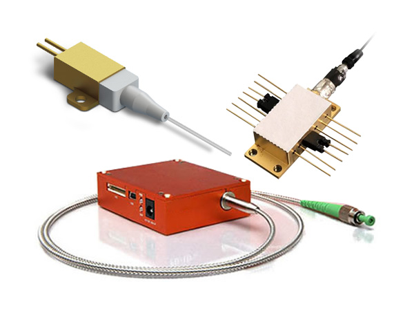
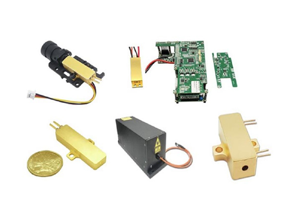
The far-field measurement instrument is a stand-alone device for measuring light intensity vs output angle of light emitting components such as high-power laser diodes, LEDs, fibers and other high-intensity light sources.
Highlights:
Wide wavelength range
Goniometric detector design
Fast scanning speed
High sampling resolution

The SFC series far-field scanner has been designed to fulfill the increasing demands on beam quality analysis and testing of light emitting components. The features of the far-field scanner include wide operating and measuring ranges. This all can be done without sacrificing speed performance – a typical measurement cycle takes only seconds, making it ideal for production testing of light emitting components.
Application:
Optical power distribution
Far-field & NA analysis measurement
Quality control of optical sources
Software Features:
Easy setting of scan parameters
Automatic archiving of results
Advanced plotting features: 1D/2D/3D & contour/polar plots
Export of data into various fi le formats: CSV, PDF, PNG, PS, XML, etc.
Numerical analysis of results
Customizable to match customer's needs
Integration into automated measurement systems
A leading supplier and manufacturer of a wide range of photonics products such as lasers,laser parts & machines.
Office: 10 Bukit Batok Crescent #07-02 The Spire Singapore 658079
Tel: +65 63167112
Fax: +65 63167113
Whatsapp: +6591904616