 English
 Français
 Deutsch
 euskara
 Русский язык
 Italiano
 Português
 Nederlands
 Polski
 Greek
Greek Lietuva
 Türkçe
 日本語
日本語 한어
한어 中文
中文 தாமில்
 فارسی
فارسی हिंदी
हिंदी Tiếng Việt
 ภาษาไทย
 Pilipino
 Indonesia
 தாமில்
Send us a message
CLOSE
WhatsApp: +65 91904616 E-mail: sales@sintec.sg


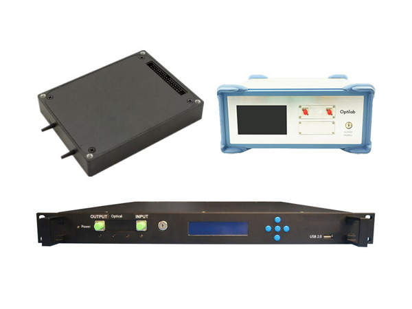
STVL Series V‑Modules
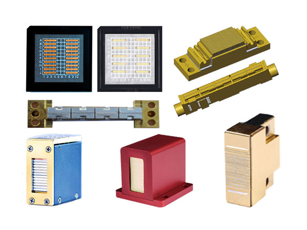
Our V‑Modules are fast, flexible, and proven. The cutting-edge performance of these industrial-grade digital light processing (DLP) subsystem is designed for new emerging applications, the DLP subsystems come with a feature-rich programming interface; it will enable impressive capabilities of your new state-of-the art product within extremely short time-to-market periods. Based on high-speed DLP controllers, DLPC410 (Discovery™4100) and DLPC910, our V‑Modules represent the highest performance class of subsystems for the DLP Advanced Light Control portfolio. Our V‑Modules offer unique flexibility in mirror control combined with outstanding pattern frequencies thanks to the sustained bandwidth of the DLPCx10 controller chipsets. The usable spectral range covers all wavelengths from 363 nm UVA to 2500 nm NIR. The Type A DMD package provides efficient cooling options enabling up to 160 W sustained optical power transfer per DMD.
Our V‑Modules enable a rapid launch into application development with DLP technology. The modules come with completely configured high-speed FPGA logic and firmware so that customers save time and costs for a dedicated hardware and firmware development. The comprehensive and long-term proven application programming interface ALP‑4 is a universal controller suite that provides full software compatibility for all V‑Modules. V‑Modules are well suited for education, academic research, proof of concept, and are used as OEM DLP subsystems for series production in a wide variety of products.
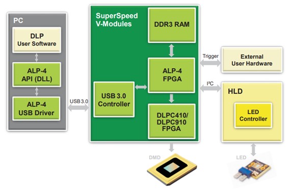
SuperSpeed V‑Modules combine maximum on-board data rates and extended on-board memory capacity with an efficient USB 3.0 computer interface. Maximum data throughput is achieved taking advantage of up to 61 Gbit/s sustained data rate of the DLPCx10 controller chipsets.
Technical Specification:
| Model | STVL-V-7001 | STVL-V-7001+ | STVL-V-9501 STVL-V-9501C | STVL-V-6501 | STVL-V-9001 STVL-V-9001C STVL-V-9001T | STVL-V-650L |
| Diagram | 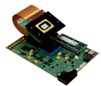 | 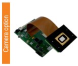 |  |  |  | 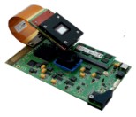 |
| Chipset | DLP7000 & DLPC410 | DLP7000 & DLPC410 | DLP9500 & DLPC410 | DLP6500 & DLPC910 | DLP9000X & DLPC910 | DLP650LNIR & DLPC410 |
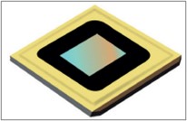
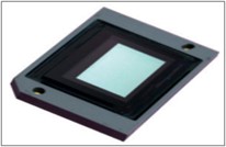
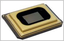
| Type A DMD | 0.7'' XGA | 0.7'' XGA | 0.95'' 1080p | 0.65'' 1080p | 0.9'' WQXGA | 0.65'' WXGA |
| Window Options | VIS, UV | VIS, UV | VIS, UV | VIS | VIS, UV | NIR |
| Micromirror Array | 1 024 x 768 | 1024 x 768 | 1 920 x 1 080 | 1 920 x 1 080 | 2 560 x 1 600 | 1 280 x 800 |
| Micromirror Pitch | 13.7 µm | 13.7 µm | 10.8 µm | 7.6 µm | 7.6 µm | 10.8 µm |
| Active Mirror Array Area | 14.0 x 10.5 mm² | 14.0 x 10.5 mm² | 20.7 x 11.7 mm² | 14.5 x 8.2 mm² | 19.4 x 12.1 mm² | 13.8 x 8.6 mm² |
| Controller Board Type | V4395 | VDIF | V4395 | V4390 | V4390 | V4395 |
| Control Board Dimensions | 162 x 99 mm² | 120 x 97 mm² | 162 x 99 mm² | 162 x 99 mm² | 162 x 99 mm² | 162 x 99 mm² |
| DMD Board Dimensions | 67 x 50 mm² | 48 x 66 mm² | 102 x 83 mm² | 101 x 78 mm² | 95 x 88 mm² | 63 x 47 mm² |
| Flexible Cable Length | 105 / 283 / 573 mm | 44 x 139 mm | 105 / 283 / 573 mm | 105 / 283 / 573 mm | 105 / (283) mm | 105 mm |
| RAM Capacity on Board | 64 Gbit / 128 Gbit | 64 Gbit / 128 Gbit | 64 Gbit / 128 Gbit | 64 Gbit / 128 Gbit | 64 Gbit / 128 Gbit | 64 Gbit / 128 Gbit |
| Binary Patterns on Board | 87381 / 174762 | 87381 / 174762 | 31 068 / 62 137 | 31 068 / 62 137 | 16 777 / 33 554 | 55 924 / 111 848 |
| Hardware Trigger | master / slave | master / slave | master / slave | master / slave | master / slave | master / slave |
| Controller Suite | ALP-4.3 | ALP-4.4 | ALP-4.3 | ALP-4.3 | ALP-4.3 | ALP-4.3 |
| Max. Switching Rate 1bit B/W | 22727 Hz | 22727 Hz | 17 857 Hz | 10 309 Hz | 12 987 Hz | 10 752 Hz |
| Max. Switching Rate 6bit Gray | 1091 Hz | 1091 Hz | 987 Hz | 871 Hz | 1 013 Hz | 856 Hz |
| Max. Switching Rate 8bit Gray | 290 Hz | 290 Hz | 266 Hz | 266 Hz | 303 Hz | 258 Hz |
| Max. Switching Rate 12bit Gray | 18 Hz | 18 Hz | 17 Hz | 17 Hz | 20 Hz | 17 Hz |
| PC Interface | USB3.0 | USB3.0 | USB3.0 | USB3.0 | USB3.0 | USB3.0 |
| PC Transfer Rate | > 4000* fps | > 4000* fps | > 1600* fps | > 1600* fps | > 1100* fps | > 3000* fps |
| Camera Port | - | 2x | - | - | - | - |
| Camera Cable Length | - | 600 / 250 mm | - | - | - | - |
| Image Sensor (on request) | - | IMX174 (IMX 422|426|536) | - | - | - | - |
| Controller Suite (Camera Option) | - | DLS-API | - | - | - | - |
*Typical value, can vary depending upon data compression ratio and PC.
The block diagram of SuperSpeed V-Modules is as shown below:
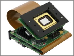
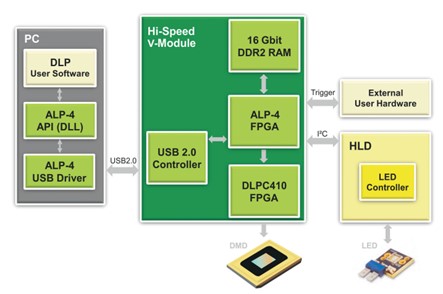
Hi‑Speed V‑Modules provide a high-performance package with small form factor. This industrially proven and cost-effective solution supports the DLP7000 chip at its maximum speed of 22 727 global array switches per second. The USB 2.0 computer interface is speeded-up by lossless compression and the on-board memory holds 21 845 binary images. The ALP‑4 Controller Suite has the complete functionality and is software compatible with the SuperSpeed V‑Modules.
Technical Specification:
| Model | STVL-V-7000 |
| DLP chip | Discovery 4100 |
| DMD Type | 0.7“ XGA 2xLVDS (DLP7000) |
| Window Options | VIS, UV |
| Micromirror Array | 1024 x 768 |
| Micromirror Pitch | 13.7 µm |
| Active Mirror Array Area | 14.0 x 10.5 mm² |
| Controller Board Type | V4100 |
| Control Board Dimensions | 71 x 68 mm² |
| DMD Board Dimensions | 67 x 50 mm² |
| Flexible Cable Length | 90 mm |
| RAM Capacity on Board | 16 Gbit |
| Binary Patterns on Board | 21845 |
| Hardware Trigger | master / slave |
| Controller Suite | ALP-4.2 |
| Array Switching Rate 1bit B/W | 22727 Hz |
| Array Switching Rate 1bit B/W | 1091 Hz |
| Array Switching Rate 8bit Gray | 290 Hz |
| PC Interface | USB 2.0 |
| PC Transfer Rate | 800 fps* |
*Typical value, can vary depending upon data compression ratio and PC.
The block diagram of high-speed V-module is as shown below:
ALP-4 Controller Suite
The ALP-4 Controller Suite is a universal platform enabling advanced control of DLP micromirror
systems. Application development is facilitated by an extensive set of library functions designed for use in industry, medicine, research and development. We launched the first ALP Controller Suite TM starting with TI's first DLP Discovery chipsets on the market in 2001. The whole line of FPGA based DLP chipsets has been supported over the years maintaining full compatibility of the application programming interface. Customers using ALP-4 can rapidly launch product design without the need of time-consuming developments for software, firmware and high-frequency FPGA logic code. The scheme of control and data flow is shown in the block diagram (a) below. The principle of operation is completely different from standard multimedia projection. Sequences of patterns are generated in the PC and uploaded to on-board memory via compressed USB transfer. Highly sophisticated FPGA logic is applied for processing and streaming the data to the micromirror array. The ALP-4 Controller Suite is included in all V-Modules, as shown in Diagram (b). It is also available as an accessory for the DLP Discovery4100 evaluation modules (EVM) of Texas Instruments.
(a)
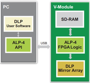
(b)
The ALP-4 application programming interface (API) provides high-level DLP control and is a proven tool supporting a wide variety of use cases from proof of concept to product development and serial products. The API is realized in a portable DLL and it can be used in C++, C#, Visual Basic (.NET), Python, MATLAB, LabVIEW, and other development platforms, Python running on a Microsoft Windows operating system.* The ALP-4.3 Controller Suite leverages the power of USB 3.0 SuperSpeed to its full extend and increases the effective transfer rate by lossless compression of patterns. Low latency updates of the micromirror array enable feedback operations via PC with ≤ 1.5 ms refresh cycle period.
The broad usability of the ALP-4.3 Controller Suite is powered by the high flexibility in pattern control. Pattern sequences can be customized in ALP-4.3 to meet respective requirements and four different modes of operation are available.
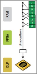
Binary Patterns
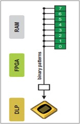
Binary pattern sequences are defined in the application program and uploaded into the on-board RAM. The timing parameters for the sequence display can be precisely controlled. ALP-4 offers high flexibility in picture time ranging from 20 µs up to several seconds. That means, mirrors can be kept still without any movement or can be switched with up to 50kHz. A comprehensive trigger facility enables the synchronization with external devices in both master or slave mode. Multiple sequences are organized in a queue for convenient parallel upload and display and are concatenated for a gapless display.
Grayscale Patterns
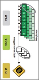
By design, the DMD is only capable to display a binary pattern at a given moment in time. To project a grayscale image, multiple binary frames have to be time controlled accordingly. ALP-4 generates patterns of gray values with the digital precision of FPGA timing. The maximum bit-depth is12bit; lower resolution can be selected. Using a synchronized detector yields perfect grayscale linearity of 10 ppm as it is typically needed in metrology applications of DLP. The grayscale pattern sequence contains the specified number of bit-planes and an efficient algorithm of pulse-width modulation (PWM) is implemented in ALP-4 that results in 260-300 fps (8 bit) for various DLP chipsets. The whole grayscale image is subject to the trigger facility so that cameras can be easily synchronized. Flex-PWM is an advanced mode of operation where the user has free control over the bit-plane timing by external trigger.
Pattern Sequence Composition
ALP-4 supports indirect frame selection by the use of a frame look-up table (FLUT). The output display sequence is composed from the patterns stored in the RAM using the FLUT entries that point to the corresponding frames. In this way the user has a maximum of flexibility in generating display sequences and can modify them by just changing the FLUT content. Repeated display of the same pattern is made possible without storing multiple copies in the RAM so that FLUT operation saves upload time and memory capacity. One of the FLUT applications is grayscale encoding by a delta-sigma approach.
Pattern Scrolling
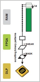
A moving DLP exposure head is state-of-the-art in industrial exposure applications like lithography and 3D-printing. Such approach requires that the patterns slide through the micromirror array with the same velocity. That is efficiently realized by uploading the stripe of pattern data to the RAM and stepping through it line by line. In this way a new DLP pattern is generated in each step by adding one line and dropping another. A significant data reduction is achieved for the upload from PC to on-board RAM. More sophisticated use cases demand for a sliding display of rotated patterns; that has been solved by additional shear operations applied on the flight. Permanent pixel masks are supported enabling modifications of the resulting pattern exposure level on the target.
Features of ALP Controller Suite
Vertical scrolling: The ALPAPI supports linearly stepping through multiple concatenated frames by an arbitrary number of rows.
Use case: Faster and more efficient use of board memory for Lithography and 3D printing applications.
Horizontal shearing: The frame can be sheared in horizontal direction (line based) by a configurable value without modifying the frame data.
Use Case: Generate a rotated image on the DMD by applying an additional shearing in vertical direction with preprocessing.
DMD mask: The DMD Mask is a monochrome bitmap that overlays ALP frames during frame display. The affected position is fixed on the DMD.
Use Case: Horizontally shape the exposure energy when scrolling vertically through a sequence of frames
Frame lookup table: Besides linear display of a sequence of frames, the ALP supports random-access order via Look up Table. Images are fully loaded only once.
Use Case: Flexible selection of projection images with low latency, as only the information of image
order is loaded.
DMD area of interest: The ALP API supports an additional display mode with reduced image data. An Area of Interest (AOI) can be selected by means of contiguous DMD rows.
Use Case: Support of an increased framerate / Improved speed.
Concatenation of frames for continuous projection: Multiple frames can be combined into one sequence.
Use Case: Displaying images continuously without any break between the projection of two
consecutive images.
Projection control by external trigger (slave mode): The transition to the next projection frame can be triggered and synchronized by an external signal.
Use Case: Chaining of several projectors or V-Modules.
Multiple customizable frame synchronization outputs: Up to three customizable synchronization signals can be generated and outputted by the V-Module.
Use Case: Trigger and synchronize external hardware, for instance as multi color light source.
PWM output: V-Modules support this with a pulse-width modulated GPIO pin (analog signal)
Use Case: Controlling a light source with an analog signal.
Option: UV, VIS
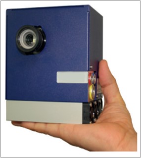
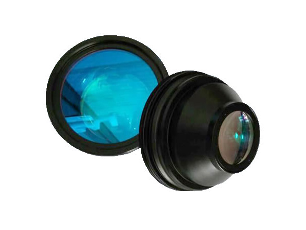
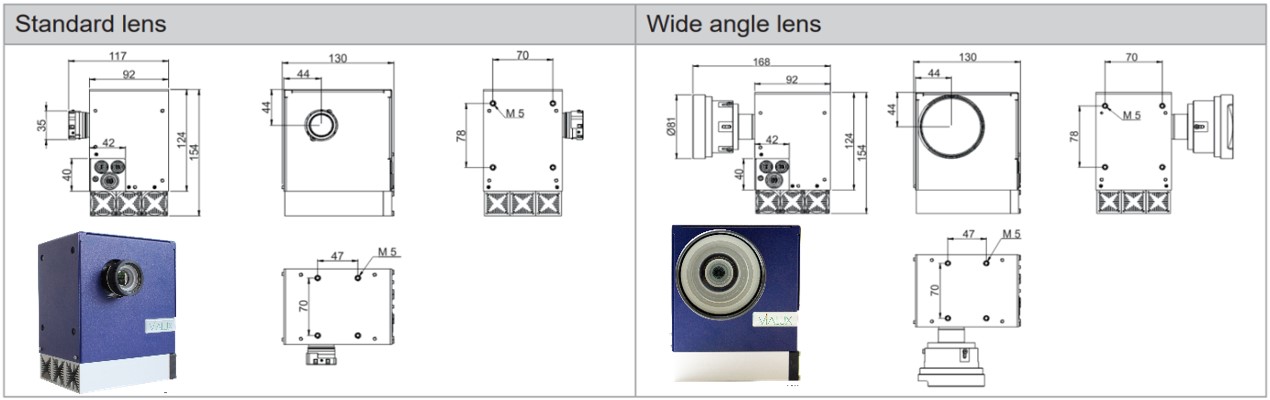
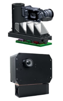
STVL-07-2.0-UV/VIS is a high performance DLP® projector based upon the Texas Instruments micromirror technology and designed to serve in demanding industrial applications. Widely used in multimedia and digital cinema since more than one decade, the well proven DLP technology has become an important tool for industrial solutions as well. The heart of this projector is a 0.7“DLP chip that consists of an array of 1024x768 mirrors. These bi-stable mirrors flip into opposite tilt positions within microseconds to generate the desired patterns. STVL-07-2.0-UV/VIS provides precise high-speed control for each individual mirror enabling outstanding flexibility and pattern frame rates of the projection output. The projector is equipped with a high-power LED light source that is the key for the compact and rugged design of the device. Typical use cases are machine vision illumination, 3D scanning, industrial exposure, and additive manufacturing. Beyond that, new emerging applications are well supported by an open SDK interface. STVL-07-2.0-UV/VIS comes with two lens options, the standard projection lens and a wide-angle lens with fixed focal length.
System Architecture
The central control unit of STVL-07-2.0-UV/VIS is USB 2.0 connected and realizes pattern upload, display, and synchronization. An integrated trigger facility supports a wide voltage range at its opto-coupler interface and is software programmable. The digital driver for the LED light source gives convenient access to power setting and temperature reading for thermal management.
System Control
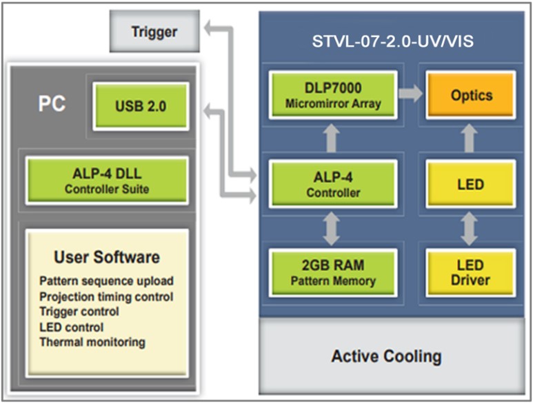
The ALP-4.2 Controller Suite is the central programming tool and provides all necessary functionality for product development. Sequences of patterns are uploaded from PC to the on-board memory via USB 2.0 transfer with lossless compression. The properties of the display sequences, e.g., bit depth, picture time, trigger mode, repetitions can be freely defined to meet the respective application requirements. The ALP-4.2 firmware streams patterns from on-board SDRAM memory to the DLP7000 micromirror array where the input pattern is one-to-one mapped to the mirrors. The patterns are updated in the global reset mode; that means all mirrors are switching simultaneously within a few microseconds. Grey value patterns are generated by controlled ON-time for each mirror yielding exact grey value linearity. The maximum global array switching rate is 22 727 fps; even higher frame rates up to 50 kHz can be achieved by partial updates of the micromirror array. Multiple STVL-07-2.0-UV/VIS devices can be run in parallel, conveniently controlled from the same application program and precisely synchronized by the trigger facility. The ALP–4.2 API is well proven and the DLL supports C++, C#, Visual Basic (.NET), Python, MATLAB, LabVIEW, and other development platforms. Microsoft® operating systems are supported up to the most recent Windows® versions both, 32-bit and 64-bit. The ALP-4 USB 2.0 driver is robust, validated, UIF compliant and 24/7 proven in industrial and medical use.
Specifications
LED options
| RED | GREEN | BLUE | VIOLET | WHITE | |
| Typical dominant wavelength | 613nm | 525nm | 460nm | 405nm | - |
| Spectral bandwidth FWHM | 19nm | 34nm | 20nm | 20nm | - |
| STVL-07-2.0-UV/VIS output* | 330lm 1450mW | 850lm 1550mW | 140lm 2550mW | - 2150mW | 1100lm - |
* Typical value for continuous projection, pulse operation may yield higher output.
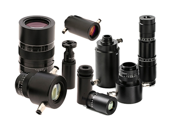
Lens options
| Mass | Distortion | Working distance | Throw ratio | Uniformity (IEC) | Contrast FOFO | MTF | |
| Standard lens | 123 g | 0.2% | 0.4m – 10m | 1.8 | +35%/-30% | 2000:1 | 45% @ 36 lp/mm |
| Wide angle lens | 580 | 5.5 | 0.5m – 2m | 0.9 | +26%/-23% | 2000:1 | 30% @ 36 lp/mm |
Frame rates
| DMD array (AOI) | 1024 x 768 | 1024 x 768 | 1024 x 768 | 1024 x 768 | 1024 x 768 | 1024 x 512 |
| Bit depth | 8-bit | 7-bit | 6-bit | 5-bit | 1-bit | 1-bit |
| Frame rate | 290 fps | 569 fps | 1091 fps | 2016 fps | 22727 fps | 30300 fps |
Greyscale linearity
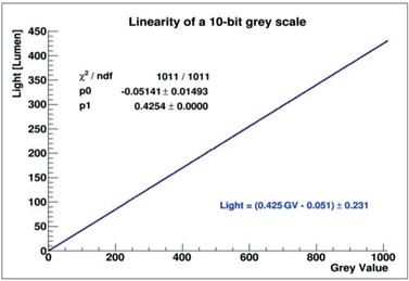
ALP-4 supports precise bit-plane timing enabling outstanding greyscale linearity in connection with synchronized camera recording. Grey value deviations are < 0.06 % of the full-scale value.
General
| Mass (without lens) | Input power | Operating temperature | Storage temperature | Regulations | LED lifetime |
| 2000 g | DC 12-24 V 150W | 10°C to 40°C Non-condensing | -10°C to 50°C Non-condensing | CE FCC Class A | >10000 h (ON time) |
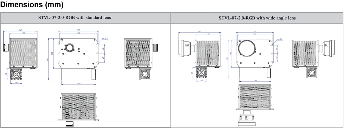
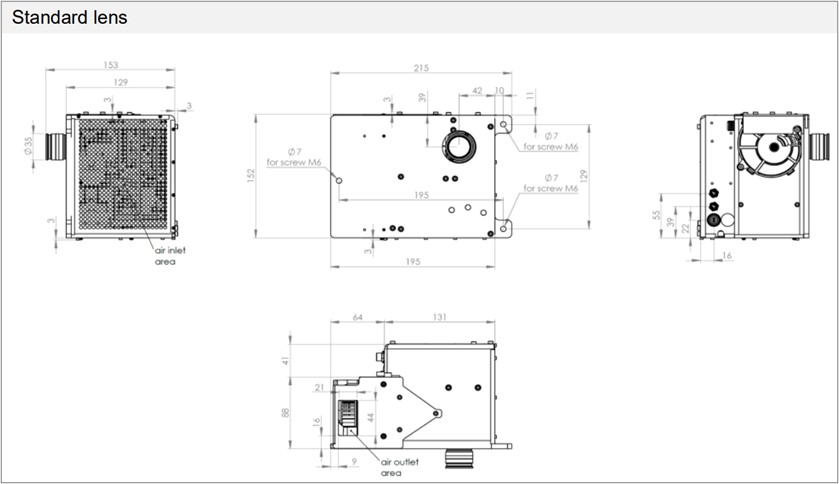
Dimension(mm)
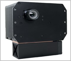
The STVL-07-2.0-RGB projector, option RGB, is equipped with three high-power LED light sources and an integrated cooling system. Typical use cases are 3D volumetric display, 3D measurement, augmented reality applications, and machine vision illumination. Beyond that, new emerging applications are well supported by an open SDK interface. STVL-07-2.0-RGB comes with two lens options, the standard projection lens with zoom capability and a wide-angle lens with fixed focal length.
System Architecture
The central control unit of STVL-07-2.0-RGB is USB 2.0 connected and realizes pattern upload, display, and synchronization. An integrated trigger facility supports a wide voltage range at its opto-coupler interface and is software programmable. The digital driver for the LED light source gives convenient access to power setting and temperature reading for thermal management.
System Control
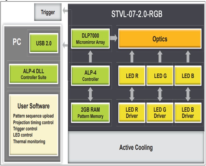
The ALP-4.2 Controller Suite is the central programming tool and provides all necessary features for advanced product development. Sequences of patterns are uploaded from PC to the on-board memory via USB 2.0 transfer with lossless compression. The STVL-07-2.0-RGB is USB 2.0 connected and realizes pattern upload, display, and synchronization. Three individual digital drivers for the three LED light sources give convenient access to power setting and temperature reading for thermal management of each single LED. In addition, each LED is gated by a programmable high-speed control line. An integrated trigger facility supports selectable voltage levels for external master or slave modes of control. The properties of the display sequences, e.g., bit depth, picture time, trigger mode, repetitions can be freely defined to meet the respective application requirements. The ALP-4.2 firmware streams patterns from on-board SDRAM memory to the DLP7000 micro mirror array where the input pattern is one-to-one mapped to the mirrors. The patterns are updated in the global reset mode; that means all mirrors are switching simultaneously within a few microseconds. Grey value patterns are generated by controlled ON-time for each mirror yielding exact grey value linearity. The maximum global array switching rate is 22 727 fps. Multiple STVL-07-2.0-RGB devices can be run in parallel, conveniently controlled from the same application program and precisely synchronized by the trigger facility. The ALP–4.2 API is well proven and the DLL supports C++, C#, Visual Basic (.NET), Python, MATLAB, LabVIEW, and other development platforms. Microsoft® operating systems are supported up to the most recent Windows® versions both, 32-bit and 64-bit. The ALP-4 USB 2.0 driver is robust, validated, UIF compliant and 24/7 proven in industrial and medical use.
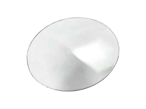
Optical and thermal design
The red, green, and blue light output of each LED is combined and fed into the homogenizer (light tunnel) by means of a dichroic mirror system. The output color of STVL-07-2.0-RGB can be RGB switched with the full frame rate. A common copper heat sink with an active cooler is included for the thermal management of the LED light sources. The temperature monitoring facility of ALP-4.2 provides all the information needed to guarantee safe LED operation within the specified limits.
Specification
LED Options
| RED | GREEN | BLUE | |
| Typical dominant wavelength | 613nm | 525nm | 460nm |
| Spectral bandwidth FWHM | 19nm | 34nm | 20nm |
| STVL-07-2.0-RGB output* | 400lm 1750mW | 850lm 1550mW | 140lm 2550mW |
* Typical value for continuous projection, pulse operation may yield higher output
Lens options
| STVL-07-2.0-RGB | Length L Diameter D Mass M | Distortion | Working distance D Throw ratio TR |
| Standard lens Part No: 9052 | L=40mm D=35mm M-120g | 0.2% | D> 0.4m TR =1.8…2.1 |
| Wide angle lens Part No: 9591 | L=91mm D=81mm M-580g | 5.5% | D> 0.5m TR = 0.9 |
Frame rates per color
| DMD array (AOI) | 1024 x 768 | 1024 x 768 | 1024 x 768 | 1024 x 768 | 1024 x 768 | 1024 x 512 |
| Bit depth | 8-bit | 7-bit | 6-bit | 5-bit | 1-bit | 1-bit |
| Frame rate | 290 fps | 569 fps | 1091 fps | 2016 fps | 22727 fps | 30300 fps |
General
| Mass (without lens) | Input power | Operating temperature | Storage temperature | Regulations | LED lifetime |
| 3200 g | DC 12-24 V 150W | 10°C to 40°C Non-condensing | -10°C to 50°C Non-condensing | CE FCC Class A | >10000 h (ON time) |
Option: UV, VIS, RGB
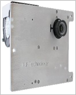
STVL-07-3.0-UV/VIS/RGB is a high performance DLP® projector based upon the Texas Instruments micromirror technology and designed to serve in demanding industrial applications. Widely used in multimedia and digital cinema since more than 20 years, the well proven DLP technology has become an important tool for industrial solutions as well. The heart of the STVL-07-3.0-UV/VIS/RGB projector is a 0.7” DLP chip that consists of an array of 1 024x768 mirrors. These bi-stable mirrors flip into opposite tilt positions within microseconds to generate the desired patterns. STVL-07-3.0-UV/VIS/RGB provides precise high-speed control for each individual mirror enabling outstanding flexibility and pattern frame rates of the projection output. The projector is equipped with a high-power LED light source that is the key for the compact and rugged design of the device. Typical use cases are machine vision illumination, 3D scanning, industrial exposure, and additive manufacturing. Beyond that, new emerging applications are well supported by an open SDK interface. STVL-07-3.0-UV/VIS/RGB comes with two lens options, the standard projection lens with zoom capability and a wide-angle lens with fixed focal length.
System Architecture
The central control unit of STVL-07-3.0-UV/VIS/RGB is USB3.0 connected and realizes pattern upload, display, and synchronization. An integrated trigger facility supports selectable voltage levels and is software programmable. The digital driver for the LED light source gives convenient access to power setting and temperature reading for thermal management.
System Control
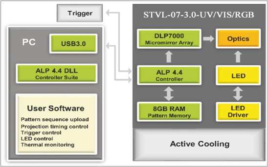
The ALP-4.4 Controller Suite is the central programming tool and provides all necessary functionality for product development. Sequences of patterns are uploaded from PC to the on-board memory via USB3.0 transfer with lossless compression. The properties of the display sequences, e.g., bit depth, picture time, trigger mode, repetitions can be freely defined to meet the respective application requirements. The ALP-4.4 firmware streams patterns from on-board SDRAM memory to the DLP7000 micro mirror array where the input pattern is one-to-one mapped to the mirrors. The patterns are updated in the global reset mode; that means all mirrors are switching simultaneously within a few microseconds. Grey value patterns are generated by controlled ON-time for each mirror yielding exact grey value linearity. The maximum global array switching rate is 22 727 fps; even higher frame rates can be achieved by partial updates of the micromirror array. Multiple STVL-07-3.0-UV/VIS/RGB devices can be run in parallel, conveniently controlled from the same application program and precisely synchronized by the trigger facility. The ALP-4.4 API is well proven for all DLPC410 chipsets; the DLL supports C++, Python LabVIEW, .NET and other development platforms. Microsoft® operating systems are supported up to the most recent Windows® versions both, 32-bit and 64-bit. The ALP-4 USB3.0 driver is robust, validated, UIF compliant and 24/7 proven in industrial and medical use.
Specifications
LED Options
| RED | GREEN | BLUE | VIOLET | WHITE | |
| Dominant wavelength | 613**nm | 525nm | 460nm | 405/385*/365*nm | - |
| Spectral bandwidth FWHM | 19nm | 34nm | 20nm | 15nm | - |
| STVL-07-3.0-RGB output* | 330lm 1450mW | 850lm 1550mW | 140lm 2550mW | - 1750/2450/2550mW | 1100lm - |
*Not available in STVL-07-3.0-RGB
** 635nm available on request
*** Typical value for continuous projection, pulse operation may yield higher output
Lens options
| Length L Diameter D Mass M | Distortion | Working distance D Throw ratio TR | Zoom | Uniformity (IEC) Contrast FOFO | MTF | |
| Standard lens | L=36mm D=35mm M-150g | 0.2% | D> 0.4m TR =1.8…2.1 | 1.00-1.16 | +25%/-30% 2000:1 | 45% @ 36 lp/mm |
Frame rates
| DMD array (AOI) | 1024 x 768 | 1024 x 768 | 1024 x 768 | 1024 x 768 | 1024 x 768 | 1024 x 512 |
| Bit depth | 8-bit | 7-bit | 6-bit | 5-bit | 1-bit | 1-bit |
| Frame rate | 290 fps | 569 fps | 1091 fps | 2016 fps | 22727 fps | 30300 fps |
Greyscale linearity
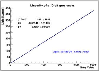
ALP-4 supports precise bit-plane timing enabling outstanding greyscale linearity in connection with synchronized camera recording. Grey value deviations are < 0.06% of the full-scale value.
General
| Mass (without lens) | Input power | Operating temperature | Storage temperature | Regulations | LED lifetime |
| 3000 g | DC 19-24 V 150W | 10°C to 40°C Non-condensing | -10°C to 50°C Non-condensing | CE FCC Class A | >10000 h (ON time) |
Dimensions [mm]
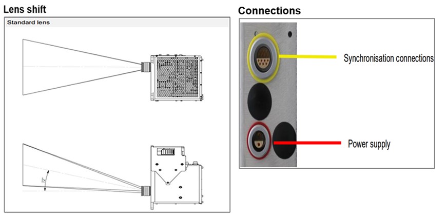
Synchronization:
| Pin | Signal | I/O | Limit | Description/ Usage |
| 1 | Dynamic Frame Trigger | Out | 5V, 10mA | outputs a dynamic frame trigger (ALP Extension DYN_SYNCH_OUT) |
| 2 | not connected | |||
| 3 | Frame Trigger | Out | 5V, 10mA | outputs one pulse per frame, e.g., for synchronizing a slave projector/camera; ALP API commands: • AlpSeqTiming (SynchDelay, SynchPulseWidth): relation to frame timing • AlpDevControl (ALP_SYNCH_POLARITY) |
| 4 | not connected | |||
| 5 | not connected | |||
| 6 | DC 5V + | Out | 5V, 350mA | supply voltage |
| 7 | not connected | |||
| 8 | not connected | |||
| 9 | not connected | |||
| 10 | DC 5V GND | GND | supply voltage ground | |
| 11 | not connected | |||
| 12 | not connected | |||
| 13 | not connected | |||
| 14 | Frame Trigger | In | 5V | triggers next frame in sequence, e.g. for synchronization with a master projector/camera ALP API commands: • AlpProjControl: ALP_PROJ_MODE=ALP_SLAVE • AlpSeqTiming (TriggerInDelay): relation to frame timing • AlpDevControl (ALP_TRIGGER_EDGE) |
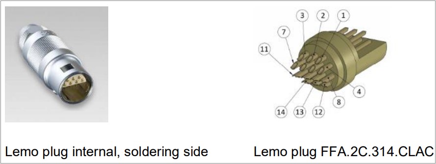
Connector: Lemo FFA.2C.314.CLAC52Z with yellow bend relief Lemo:GMA.1B.045.DJ
Cable: 7x0,14 mm² multiconductor shielded cable, grey, diameter 5.0 mm, Lemo: 070140

Power supply:
| Pin | Signal | Description / Usage |
| 1 | GND | Ground |
| 2 | +19…24 V | Positive power supply |
Connector:Lemo FFA.1S.302.CLAK82Z with red bend relief Lemo:GMA.2B.070.DR
Cable:2x0,5 mm² (AWG20) with shield, diameter 7,2 … 8,2 mm
Power supply unit (Example): XP-Power AHM150PS19
USB 3.0:se only USB3.0 cable with high quality, Maximum cable length 3 m
Option: UV, VIS, NIR
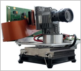
STVL-3.0-EVM-UV/VIS/NIR monochrome LED light engine is a high performance DLP® projector based upon the Texas Instruments micromirror technology and designed to serve in demanding industrial or research applications.
STVL-3.0-EVM-UV/VIS/NIR is available with the following V-Modules:
STVL-V-6501 VIS
STVL-V-650L NIR
STVL-V-7001 VIS/UV
 | The STVL-V-6501 VIS is based on a 0.65’’ 1080p DLP chip (DLP6500) and the DLPC910 controller enabling binary pattern rates up to 10 309 Hz in the visible range (400 - 700 nm) with a light power density up to 25 W/cm² |
 | Featuring a 0.65” WXGA DLP chip (DLP650LNIR) and the DLPC410 controller the STVL-V-650L NIR supports binary pattern rates up to 10752 Hz in near-infrared range (800 - 2000 nm) with light power density up to 500 W/cm² between 950 nm - 1150 nm. |
 | With its 0.7“XGA DLP chip (DLP7000/DLP7000UV) and the DLPC410 controller the STVL-V-7001 VIS/UV creates binary patterns up to 22 727 Hz in the visible range (400 - 700 nm) or alternatively in the ultraviolet-range (363 - 420 nm). |
System Architecture
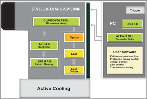
The central control unit of STVL-3.0-EVM-UV/VIS/NIR is USB 3.0 connected and realizes pattern upload, display, and synchronization. An integrated trigger facility supports a wide voltage range at its opto-coupler interface and is software programmable. The digital driver for the LED light source gives convenient access to power setting and temperature reading for thermal management.
STVL-3.0-EVM-UV/VIS/NIR monochrome LED light engines are based upon the STAR CORE optics, a cooling system, the ALP-4.3 software, and integrate a high-power LED including the LED driver for up to 24 A.
The following LED wavelengths are available for:
λ [nm] = 405 / 460 / 525 / 615 / White (DLP6500)
λ [nm] = 730 / 850 / 940 (DLP650LNIR)
λ [nm] = 405 / 460 / 525 / 615 / White (DLP7000)
λ [nm] = 365 / 385 / 405 (DLP7000UV)
The LED driver of STVL-3.0-EVM-UV/VIS/NIR is controlled by I²C commands for setting the LED current and reading the LED thermistor output and seamlessly integrates with our V-Modules.
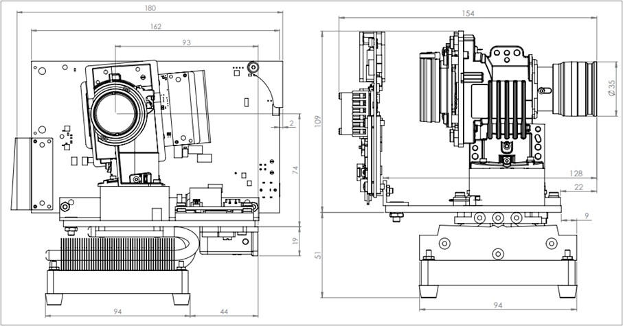
Dimensions of STVL-3.0-EVM-UV/VIS/NIR [mm]
with SuperSpeed STVL-V-650L NIR (as an example)
Power supply
STVL-3.0-EVM-UV/VIS/NIR comes with its own power supply designed for the LED driver with a maximum output of 24 A DC.
Specifications:
Input 100 – 240 V ~ 2 A, 50 – 60 Hz Output 19 V / 7.89 A
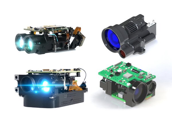
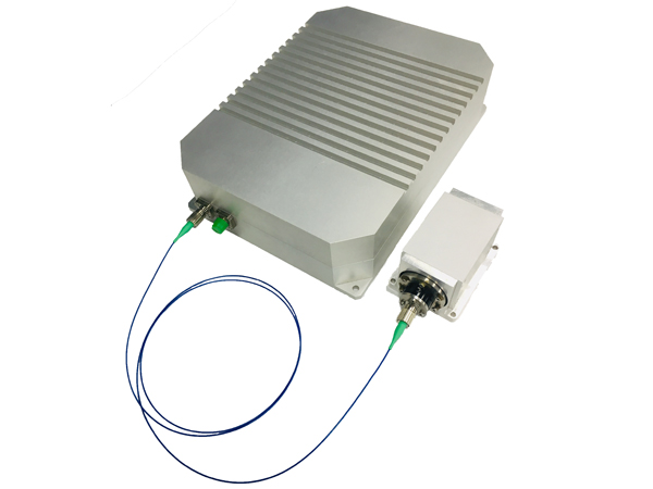
A Marriage of Projector and Camera for Next Generation Imaging Solutions
The success of digital image processing solutions depends on both, the imaging device and appropriate illumination. Frequently, specifically structured light patterns are required and ®DLP micro-mirror projection turned out to be fast, flexible and proven for that purpose. Multiple different devices, projectors and cameras, used to be combined for pattern generation and image sensing. Such setups cause challenges for precise synchronization and computer interfacing. We have linked together the image sensor chips and the DLP micro-mirror device into the same electronic control circuitry resulting in ONE integrated device. This Direct Link Sensor (DLS) represents a new class of imaging tools enabling advanced vision solutions.
DLS Principle of Operation
Our FPGA logic controls both the high-performance DLP chip for fast and precise pattern projection and the image sensors for digital imaging. In that way pattern generation and image recording are precisely synchronized, also for partial sensor readout in a region of interest. Frame rates vary from 166 fps to 5150 fps (ROI) for each camera in parallel. The schematic below shows the DLS architecture with the major data flow.
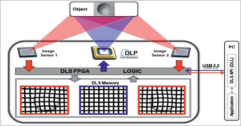
A sequence of user-defined projection patterns is uploaded into the DLS memory (RAM) and the data can be used for a single projection or for a projection loop. The illuminated object is recorded by the sensors and the images are buffered in the on-board RAM that holds up to 1 592 pictures (10 bit,1920 x 1200 pixels), ready for download to the PC for further processing. All data flow operations are executed by one FPGA device enabling the outstanding real-time precision. Streaming data to and from the on-board RAM is realized by the USB3.0 SuperSpeed transfer implemented on the DLS system. The upload is further enhanced by lossless on the fly compression and pixel binning is available as an option for image download.
A custom application program controls the DLS system through the DLS API, an application development interface supporting rapid system development. The DLS API is implemented as a dynamic-link library (DLL) and the functions are designed to build an application with a minimum of programming effort providing maximum control capabilities at the same time. The user can define any type of pattern sequence that may differ in bit depth, number of pictures, and frame rate. The DLS principle of operation offers significant advantages for machine vision applications requiring flexible scene illumination:
Projection and imaging components are precisely synchronized
High bandwidth transfers are running independent from PC
Hardware integration guarantees real-time data flow
The DLS-Module requires only one USB3.0 interface
The clear API software facilitates rapid application development
Specifications of DLS system
| DLP projection chipset | |||
| DLP7000 micro-mirror array, 1024 x 768 mirrors | |||
| Max. pattern update rate, 22727 fps (full array) | |||
| Image sensor chip | |||
| Sony Pregius IMX-174, 1920 x 1200 pixels | |||
| Max. image buffer capacity, 1592 full resolution, 10 bit images. | |||
| DLS frame rates (selected regions of interest – ROI) | |||
| Image sensor lines (ROI) | DLS frame rate | Image sensor bit depth | DLP projector bit depth |
| 1200 | 166fps | 10 bit | 8 bit |
| 676 | 289 fps | 10 bit | 8 bit |
| 374 | 500 fps | 10 bit | 7 bit |
| 236 | 750 fps | 10 bit | 6 bit |
| 168 | 1000 fps | 10 bit | 6 bit |
| 70 | 1900 fps | 10 bit | 5 bit |
| 2 | 5150 fps | 10 bit | 2 bit |
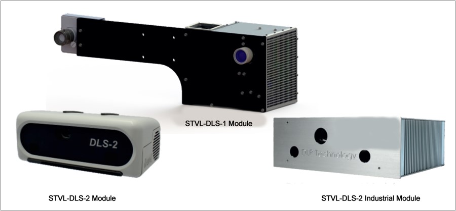
Models
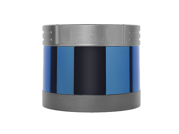
The STVL-DLS-1 and STVL-DLS-2 Modules address different field of view and working distance (WD), respectively. The diagonal field of view (DFOV) is given by DFOV = 0.69 x WD. The STVL-DLS-1. The STVL-DLS-2 Industrial Module is a version of STVL-DLS-2 Module. The STVL-DLS-2 Industrial Modules is equipped with a dust-proof housing and passive cooling for industrial use cases. Long lasting high-power LEDs form the light source for the two DLS-Modules.
An additional software package zSnapper SDK (zSn.dll) is available as an optional extension for our DLS-Modules enabling high-speed and high-precision 3D coordinate acquisition. This powerful 3D measurement software has been developed for our 3D scanners and is now released on module level. It delivers (x, y, z) coordinates directly and automatically for use in 3D machine vision.
| Product | Throw ratio (WD/FoV) | Working distance (mm) | Base length (stereo base) (mm) | Configuration | LED Color Option | Software Option |
| STVL-DLS-1 Module | 1.8 | 1300-3000 | 410 | 1 x DLP7000, 1 x Sony IMX174 | standard: white 460 nm blue 730 nm NIR 850 nm NIR | P/N 9623 zSnapper® SDK software |
| STVL-DLS-2 Module | 1.8 | 600 or 1000 | 160 | 1 x DLP7000, 2 x Sony IMX174 | standard: white 460 nm blue 730 nm NIR 850 nm NIR | P/N 9623 zSnapper® SDK software |
| STVL-DLS-2 Industrial Module | 1.8 | 600 or 1000 | 160 | 1 x DLP7000, 2 x Sony IMX174 | standard: white 460 nm blue 730 nm NIR 850 nm NIR | P/N 9623 zSnapper® SDK software |
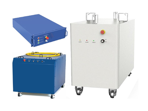
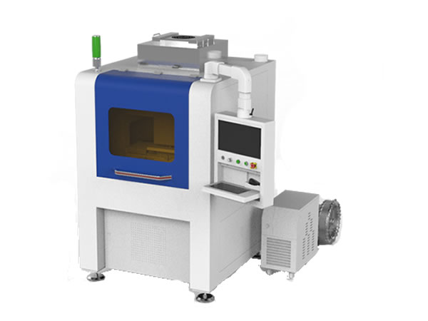
3D imaging scanning system products
One of the application of our 3D scanning system is used in the areas of compression garments, whole-body measurement, prosthetics, orthopedic technology and posture analysis. This system offers the user a user-friendly user interface and is characterized by its ease of use. The system is not tied to a specific location, can be stowed away in a space-saving manner and is immediately ready for use after assembly.
(A)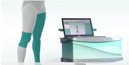 | 3D Body Measurement consists of 3D scanning system which is a solution optimized for use in medical supply stores to supply customers with compression products. The scanning system consists of a mobile equipment trolley and the plugin. |
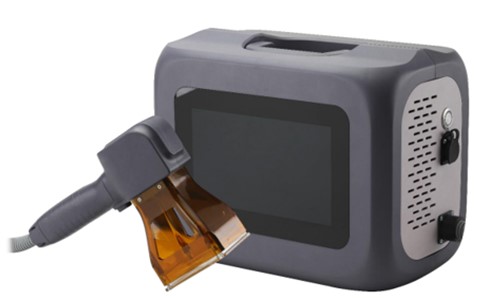
(B) | The Link is a mobile extension to the 3D scanning system which enables location-independent, mobile data acquisition of skin and tensile dimensions for the supply of circular and flat knitted products. Customer data and manual measurements are recorded in the tablet and transferred back to the store directly into the instrument’s software. The entire range of the system is available for fast, digital processing of the ordering process. |
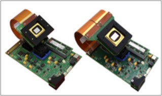
(C) 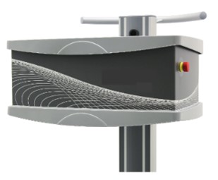 | Compact 3D Scanning System is specially adapted to the needs of pharmacies, both in terms of space requirements and the range of functions of the software. The reduced working distance allows the 3D scanning system to be used in a smaller rooms. If the device is not needed, it can be stowed away quickly and in a space-saving manner. |
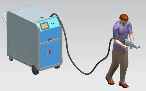
(D) 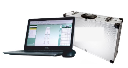 | With Light Scanning System, we want to give our customers the opportunity to use the advantages of the scanning’s software in the supply of compression stockings immediately after a product demonstration. With the transfer of the manually determined dimensions, all subsequent steps from product configuration to the transfer of the dimensions in online shops or to the ERP software are available to the user in the software. This product can be purchased as a stand-alone product if the premisses in the medical supply store do not offer enough space for the 3D scanning system. |
Please contact us for more information.
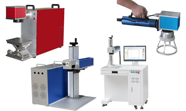
A leading supplier and manufacturer of a wide range of photonics products such as lasers,laser parts & machines.
Office: 10 Bukit Batok Crescent #07-02 The Spire Singapore 658079
Tel: +65 63167112
Fax: +65 63167113
Whatsapp: +65 91904616